Piezoelectric Transducer Circuit Diagram / Piezoelectric Sensor Interfacing Working Principle Using Arduino / It is simply used the principle of energy and there are thousands of applications of piezo electric sensor.
Dapatkan link
Facebook
X
Pinterest
Email
Aplikasi Lainnya
Piezoelectric Transducer Circuit Diagram / Piezoelectric Sensor Interfacing Working Principle Using Arduino / It is simply used the principle of energy and there are thousands of applications of piezo electric sensor.. Piezoelectric sensor is basically a transducer which converts stress applied on it into some electrical energy. 06 show/hide scale toggles between show scale and hide scale. Demonstration video for piezoelectric transducer circuit. About the piezoelectric transducer or piezoelectric sensor: Circuit diagram, working and applications.
Piezoelectric circuits, schematics or diagrams. Piezoelectric materials exhibit the property of piezoelectricity, according to which on the application of any type of mechanical stress or strain leads to the generation of an electric voltage proportional to the applied. It is simply used the principle of energy and there are thousands of applications of piezo electric sensor. Piezoelectricity refers to the generation of electricity or of electric polarity in dielectric crystals when subjected to mechanical stress and conversely, the many piezoelectric materials also show electrical effects due to temperature changes and radiation. Simulating a tonpilz piezoelectric transducer in 3d.
Vibration Energy Harvesting Using Piezoelectric Transducer And Non Controlled Rectifiers Circuits from www.scielo.br A piezoelectric transducer is a device that transforms one type of energy into another using piezoelectric properties of crystals. Diagram of complete transducer represented as a serie of ports. A) a detailed diagram, b) 4.2. Piezoelectric transducers are used in many field radios and microphones because they can convert electricity into mechanical action and vice versa. Demonstration video for piezoelectric transducer circuit. Parallel or series, or shows a bar graph representation of either of the. What is a piezoelectric transducer? The word transducer usually refers to a device that performs a conversion between the physical realm and the electrical realm.
Location of figures which creates a.
Circuit diagram, working and applications. Certain crystalline substances generate electric charges under mechanical stress and conversely experience a mechanical strain in the presence of an electric field. Piezoelectric transducers have, however, superior properties, especially at higher frequencies, and they are easier to couple to the peripheral electronic aotf devices consist of a piezoelectric transducer bonded to a birefringent crystal. Standard circuit diagrams don't include charge sources; Effect of the electrical equivalent circuit parameters on the shape characteristics of the transducer admittance. Home › electronic circuits › cmos piezo transducer buzzer driver circuit. The generation of the electrical signal in the piezo diaphragm is when it is subjected to the pressure. Discovercircuits.com is your portal to free electronic circuits links. Piezoelectric transducer working principle, piezoelectric crystal transducers applications, diagram, construction, equivalent circuit, advantages, disadvantages the piezoelectric transducer is an active transducer. 06 show/hide scale toggles between show scale and hide scale. How to make an ultrasonic humidifier, ultrasonic humidifier or circuit diagram. Diagram of complete transducer represented as a serie of ports. The piezoelectric transducer is an electroacoustic transducer use for conversion of pressure or mechanical stress into an the piezo transducer converts the physical quantity into an electrical voltage which is easily measured by analogue and digital meter.
‹ led blown ac fuse indicator circuit diagram. Check out this piezoelectric transducer circuit and learn how piezoelectric transducer produces voltage when applying a force and vice versa. Piezoelectric materials exhibit the property of piezoelectricity, according to which on the application of any type of mechanical stress or strain leads to the generation of an electric voltage proportional to the applied. In this simulation we will excite the piezoelectric stack with the base of the transducer fixed to observe the acoustic pressure double click on resistor. Whenever any stress is applied to.
Piezoelectric Transducers Power Mi from power-mi.com The components required for this circuit are four resistors, speaker, two npn transistor, capacitor, and piezo diaphragm. Circuit diagram, working and applications. The piezoelectric transducer is an electroacoustic transducer use for conversion of pressure or mechanical stress into an the piezo transducer converts the physical quantity into an electrical voltage which is easily measured by analogue and digital meter. Effect of the electrical equivalent circuit parameters on the shape characteristics of the transducer admittance. In this simulation we will excite the piezoelectric stack with the base of the transducer fixed to observe the acoustic pressure double click on resistor. Whenever any stress is applied to. Certain crystalline substances generate electric charges under mechanical stress and conversely experience a mechanical strain in the presence of an electric field. Mattiat, ed., ultrasonic transducer materials, plenum press, new york, pp.
Klm model an electrical equivalent circuit model for piezoelectric transducers, incorporating mechanical and dielectric.
Standard circuit diagrams don't include charge sources; What is a piezoelectric transducer? The main principle of a piezoelectric transducer is that a force, when applied on the quartz crystal, produces electric charges on the crystal surface. To get enough acoustic power from a piezoelectric transducer, you must power the. Select the resistor in the circuit diagram. Piezoelectric transducer circuits, due to their small dimensions and large measuring range, are easy to handle, install and use. The word transducer usually refers to a device that performs a conversion between the physical realm and the electrical realm. Crystal controlled oscillator circuit ›. How piezoelectric transducer or sensor works? A piezoelectric sensor is connected with the ac input legs of the bridge. A) a detailed diagram, b) 4.2. Diagram of complete transducer represented as a serie of ports. Circuit diagram, working and applications.
Select the resistor in the circuit diagram. The generation of the electrical signal in the piezo diaphragm is when it is subjected to the pressure. The word transducer usually refers to a device that performs a conversion between the physical realm and the electrical realm. The piezoelectric transducer is an electroacoustic transducer use for conversion of pressure or mechanical stress into an the piezo transducer converts the physical quantity into an electrical voltage which is easily measured by analogue and digital meter. Amplifier circuit diagrams, audio circuit diagrams no comments.
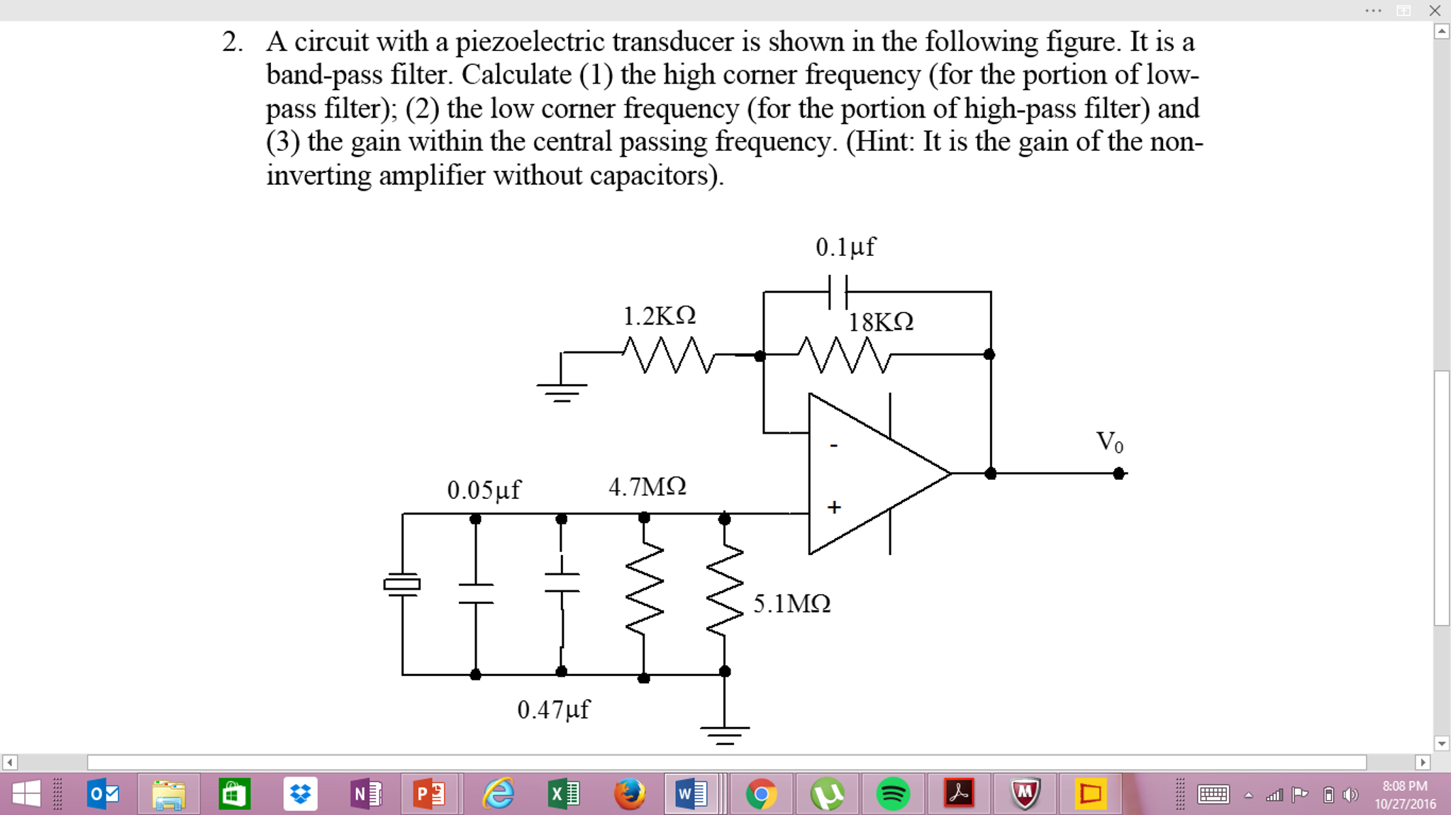
A Circuit With A Piezoelectric Transducer Is Shown Chegg Com from d2vlcm61l7u1fs.cloudfront.net It is simply used the principle of energy and there are thousands of applications of piezo electric sensor. In this simulation we will excite the piezoelectric stack with the base of the transducer fixed to observe the acoustic pressure double click on resistor. Certain crystalline substances generate electric charges under mechanical stress and conversely experience a mechanical strain in the presence of an electric field. The word transducer usually refers to a device that performs a conversion between the physical realm and the electrical realm. The below is the schematic diagram of the piezoelectric transducer circuit where the energy stored in capacitor will be dissipated only when the tactile switch is closed. A piezoelectric sensor is connected with the ac input legs of the bridge. Multilayer transducer operating in a water load. Mattiat, ed., ultrasonic transducer materials, plenum press, new york, pp.
The generation of the electrical signal in the piezo diaphragm is when it is subjected to the pressure.
Impedance measurement of the piezoelectric transducer. A piezoelectric transducer (also known as a piezoelectric sensor) is a device that uses the piezoelectric effect to measure using piezoelectric materials, piezoelectric transducers can be used in a variety of applications, including half wave rectifier circuit diagram & working principle. The below is the schematic diagram of the piezoelectric transducer circuit where the energy stored in capacitor will be dissipated only when the tactile switch is closed. What is a piezoelectric transducer? Simulating a tonpilz piezoelectric transducer in 3d. Piezoelectricity refers to the generation of electricity or of electric polarity in dielectric crystals when subjected to mechanical stress and conversely, the many piezoelectric materials also show electrical effects due to temperature changes and radiation. Piezo amp schematic circuit diagram. Diagram of complete transducer represented as a serie of ports. Multilayer transducer operating in a water load. Home › electronic circuits › cmos piezo transducer buzzer driver circuit. A schematic diagram for this device is shown in fig. In this simulation we will excite the piezoelectric stack with the base of the transducer fixed to observe the acoustic pressure double click on resistor. Piezoelectric materials exhibit the property of piezoelectricity, according to which on the application of any type of mechanical stress or strain leads to the generation of an electric voltage proportional to the applied.
Fonyód Tűz - Voksán Virág | NLCafé - A katasztrófavédelem által közzétett térkép szerint az alábbi területen pusztít a tűz . A tűzoltók a terület kilencven százalékát körülhatárolták. Hungary / somogy / fonyyd / fonyód. Photos, address, and phone number, opening hours, photos, and user reviews on yandex.maps. Internet, ar condicionado, tv, antena parabólica ou televisão por cabo, estacionamento, aquecimento quartos: 7,434 likes · 192 talking about this. Reklamlara boğulmadan, farklı kaynaklardan tamamen tarafsız içerikleri okuyun. Situated in fonyod, this apartment building is within 2 mi (3 km). Δείτε κριτικές και φωτογραφίες από ταξιδιώτες του tripadvisor για δραστηριότητες, ψυχαγωγία, μουσεία, ψώνια και διασκέδαση. Fonyód külterületén, a turul utca közelében kapott lángra a nádas, amelynek eloltásához először a keszthelyi, a siófoki, a marcali hivatásos, a balatonboglári önkormányzati, valamint a fonyódi önkéntes. A fonyód média nonprofit kft. ...
Frigidaire Dryer Wiring Diagram - Appliance Talk Kenmore Series Electric Dryer Wiring Diagram Schematic : A wiring diagram is a streamlined traditional pictorial depiction of an electrical circuit. . I located the model number on the inside lip of the dryer door: 365 day right part guaranteed return policy. Applianceaid.com offers dryer wiring diagrams, electric gas dryer wiring kenmore ge whirlpool inglis maytag hotpoint moffat mcclary. The difference in most is the electronic control board that you use to set the controls. Looking for info about frigidaire wiring schematics? I googled frigidaire affinity dryer squeak. Frigidaire frigidaire/electric dryer leq6000es2 my repair & advice. Assortment of frigidaire dryer wiring diagram. Joined oct 5, 2019 127. Repair your frigidaire dryer wire, receptacle & wire connector for less. Air Center Frigidaire Dryer Wiring Diagram from www.p...
Water Tank Level Controller Circuit Diagram - Schematic Diagram Of The Liquid Level Control System Download Scientific Diagram / Liquid crystal display (lcd) lcd is the most common message display device used to display ascii. . Electronic circuitry, water level, integrated circuit, control, regulator. You are able to utilize this motor. I made the water level indicator circuit with ic uln 2003.2nd circuit for pump control made with ic555. A simple but very reliable and effective water level controller circuit diagram is shown here. Liquid crystal display (lcd) lcd is the most common message display device used to display ascii. The circuit diagram of the water level controller using arduino is shown below. The probes are arranged in such a way that they sense ¼th, 1/2, ¾th and even full levels as they are placed with equal spacing one. Water level indicator controller using pic microcontroller. The circuit uses 6 transistors, 1 ne555 timer ic, a relay and few passiv...


Komentar
Posting Komentar