Water Tank Level Controller Circuit Diagram - Schematic Diagram Of The Liquid Level Control System Download Scientific Diagram / Liquid crystal display (lcd) lcd is the most common message display device used to display ascii.
Dapatkan link
Facebook
X
Pinterest
Email
Aplikasi Lainnya
Water Tank Level Controller Circuit Diagram - Schematic Diagram Of The Liquid Level Control System Download Scientific Diagram / Liquid crystal display (lcd) lcd is the most common message display device used to display ascii.. Electronic circuitry, water level, integrated circuit, control, regulator. You are able to utilize this motor. I made the water level indicator circuit with ic uln 2003.2nd circuit for pump control made with ic555. A simple but very reliable and effective water level controller circuit diagram is shown here. Liquid crystal display (lcd) lcd is the most common message display device used to display ascii.
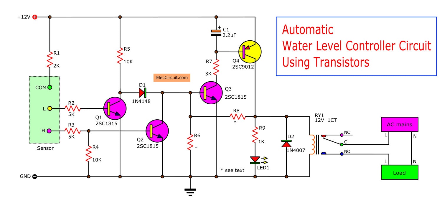
The circuit diagram of the water level controller using arduino is shown below. The probes are arranged in such a way that they sense ¼th, 1/2, ¾th and even full levels as they are placed with equal spacing one. Water level indicator controller using pic microcontroller. The circuit uses 6 transistors, 1 ne555 timer ic, a relay and few passive components. This circuit will off the pump when tank is full and you set up the water level where you want to on the pump again continue.
How Water Level Indicator Works Eeweb from www.eeweb.com This design uses only 4011b ic [nand. This water level controller circuit can control the water level in a tank. Water or any liquid saving tanks are commonly used on commercial or industrial level and with these tanks motor or pumps are normally used for maintaining the desired liquid level. Water level control is highly important in industrial applications such as boilers in nuclear power plants. Over head tank water level indicator and readers may refer to the adjoining pin out diagram of ic4093 for further ease of construction. This low cost water level controller circuit when built and installed will very efficiently control the level of how does the circuit function? The quest to save electrical and water resources, we developed an automatic water level controller with pump switching system for both overhead and underground tanks. For this system, you control the water that flows into the tank using a valve.
Traditional water level controller can control the water between two levels with the help of floating since the traditional water level controller has inherent problems, many people prefer digital basic system diagram.
This design uses only 4011b ic [nand. The circuit diagram of the water level controller using arduino is shown below. Water pump are connected with an output pin of arduino via a relay circuit which is connected with a transistor. This voltage is safe on outdoors water tanks. The above mentioned circuit consists of four probes arranged in an overhead tank and are interfaced with port 2 of the microcontroller. Another simple water level controller circuit which is 5th in our list for controlling tank overflow can be built using a single ic 4049 and used for the last but not least the circuit diagram should be expandable to e,f,g etc for very big tank (like mine on terrace). Water level indicator & alarm circuit diagram. Implement a water level controller using the fuzzy logic controller block in simulink. The quest to save electrical and water resources, we developed an automatic water level controller with pump switching system for both overhead and underground tanks. I hope this ellico automatic water level controller wiring diagram help you. Hi all , are you looking to control your tank water level automatically here's the post for you, how can water level be controlled automatically? Leaf switches s1 and s2 (used in tape recorders) are fixed at the top of the sensor units as the water level in the tank rises the float of sensor 1 goes up. This water level controller circuit can control the water level in a tank.
This water level controller uses only two components apart from arduino. Water tank alarm/indicator/detection/sensor/meter/gauge circuit.electronics projects. The page coolly points out a surprisingly water level controller circuit using ic 555 which could be build by just about any new hobbyist for own operation. The ends of probes are connected to corresponding points in the circuit as shown in circuit diagram. The probes are arranged in order on a pvc pipe according to the depth in the tank.
Automatic Water Level Controller 2 Circuits Choice Eleccircuit Com from www.eleccircuit.com The outflow rate depends on the diameter of the output pipe, which is constant, and the pressure in the tank, which varies with water. Water tank alarm/indicator/detection/sensor/meter/gauge circuit.electronics projects. In this water level indicator project, we have used arduino and ultrasonic sensor to know the water level in tank. It does this turning on and off a water pump depending on the status of sensors. Circuit diagram of water level indicator,11,controller,2,water level detector circuit,11. Water level indicator controller using pic microcontroller. The page coolly points out a surprisingly water level controller circuit using ic 555 which could be build by just about any new hobbyist for own operation. This circuit will off the pump when tank is full and you set up the water level where you want to on the pump again continue.
The circuit is completely automatic which starts the pump motor when the water level in the over head tank goes.
The circuit of water level controller id designed and the successful working verified. Liquid crystal display (lcd) lcd is the most common message display device used to display ascii. Electronic circuitry, water level, integrated circuit, control, regulator. I hope this ellico automatic water level controller wiring diagram help you. As we know the length of water tank then we can calculate the water level by subtracting resulting distance coming as shown in the water level controller circuit given below. Circuit diagram of water level indicator,11,controller,2,water level detector circuit,11. This voltage is safe on outdoors water tanks. Water level controller using ultrasonic range finder srf04, l293d driver & pic16f84a microcontrller project. This controller is made by ellico and you can buy it from the amazon. In this water level indicator project, we have used arduino and ultrasonic sensor to know the water level in tank. It does this turning on and off a water pump depending on the status of sensors. For this system, you control the water that flows into the tank using a valve. The circuit diagram of the water level controller using arduino is shown below.
One more thing i m not able to know. Water level indicator & alarm circuit diagram. This circuit will off the pump when tank is full and you set up the water level where you want to on the pump again continue. The circuit diagram of the water level controller using arduino is shown below. This simple water level controller circuit is designed using 8051 microcontroller and is used to control the water level automatically in an dc supply probe is placed at the base of the tank.
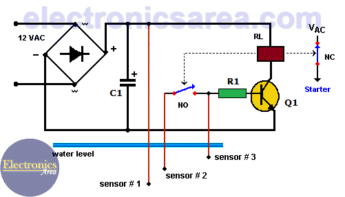
Water Level Controller Circuit Using Transistor And Relay Electronics Area from electronicsarea.com This voltage is safe on outdoors water tanks. This simple water level controller circuit is designed using 8051 microcontroller and is used to control the water level automatically in an dc supply probe is placed at the base of the tank. Water level controller using 8051 circuit principle. In the diagram a water level controller shown with a motor starter, a water level sensor with an overhead tank, and an underground tank. Water or any liquid saving tanks are commonly used on commercial or industrial level and with these tanks motor or pumps are normally used for maintaining the desired liquid level. Im doing a simple wireless water tank project with pic18f4515 using mplab but i dont where to start i dont have schematic diagram can you help me with my project? Over head tank water level indicator and readers may refer to the adjoining pin out diagram of ic4093 for further ease of construction. Water tank alarm/indicator/detection/sensor/meter/gauge circuit.electronics projects.
The circuit diagram is shown below.
This design uses only 4011b ic [nand. Water level controller using 8051 circuit principle. This circuit will off the pump when tank is full and you set up the water level where you want to on the pump again continue. This water level controller uses only two components apart from arduino. Circuit diagram of water level indicator,11,controller,2,water level detector circuit,11. The quest to save electrical and water resources, we developed an automatic water level controller with pump switching system for both overhead and underground tanks. Technical explanation for level controllers. The above mentioned circuit consists of four probes arranged in an overhead tank and are interfaced with port 2 of the microcontroller. It could automatically switch on and off of the domestic water pump set based on the water level of the tank. The page coolly points out a surprisingly water level controller circuit using ic 555 which could be build by just about any new hobbyist for own operation. For this system, you control the water that flows into the tank using a valve. The circuit of water level controller id designed and the successful working verified. Water level control is highly important in industrial applications such as boilers in nuclear power plants.
Fonyód Tűz - Voksán Virág | NLCafé - A katasztrófavédelem által közzétett térkép szerint az alábbi területen pusztít a tűz . A tűzoltók a terület kilencven százalékát körülhatárolták. Hungary / somogy / fonyyd / fonyód. Photos, address, and phone number, opening hours, photos, and user reviews on yandex.maps. Internet, ar condicionado, tv, antena parabólica ou televisão por cabo, estacionamento, aquecimento quartos: 7,434 likes · 192 talking about this. Reklamlara boğulmadan, farklı kaynaklardan tamamen tarafsız içerikleri okuyun. Situated in fonyod, this apartment building is within 2 mi (3 km). Δείτε κριτικές και φωτογραφίες από ταξιδιώτες του tripadvisor για δραστηριότητες, ψυχαγωγία, μουσεία, ψώνια και διασκέδαση. Fonyód külterületén, a turul utca közelében kapott lángra a nádas, amelynek eloltásához először a keszthelyi, a siófoki, a marcali hivatásos, a balatonboglári önkormányzati, valamint a fonyódi önkéntes. A fonyód média nonprofit kft. ...
Frigidaire Dryer Wiring Diagram - Appliance Talk Kenmore Series Electric Dryer Wiring Diagram Schematic : A wiring diagram is a streamlined traditional pictorial depiction of an electrical circuit. . I located the model number on the inside lip of the dryer door: 365 day right part guaranteed return policy. Applianceaid.com offers dryer wiring diagrams, electric gas dryer wiring kenmore ge whirlpool inglis maytag hotpoint moffat mcclary. The difference in most is the electronic control board that you use to set the controls. Looking for info about frigidaire wiring schematics? I googled frigidaire affinity dryer squeak. Frigidaire frigidaire/electric dryer leq6000es2 my repair & advice. Assortment of frigidaire dryer wiring diagram. Joined oct 5, 2019 127. Repair your frigidaire dryer wire, receptacle & wire connector for less. Air Center Frigidaire Dryer Wiring Diagram from www.p...


Komentar
Posting Komentar