Rv Inverter Wiring Diagram / Power Inverter Installation Diagrams Wiring Library / A wiring diagram is a simplified traditional photographic depiction of an electric circuit.
Dapatkan link
Facebook
X
Pinterest
Email
Aplikasi Lainnya
Rv Inverter Wiring Diagram / Power Inverter Installation Diagrams Wiring Library / A wiring diagram is a simplified traditional photographic depiction of an electric circuit.. How to choose the right inverter for your rv and how to go about installing it? Diy wiring diagrams for 100w, 200w, 300w, 400w, 600w, 800w kits. Today we install the we have diagrams on the website to be able to install it with a manual or automatic switch or install. Installing aims inverter part 3 wiring diagram. The high frequency ac to low frequency ac converter circuit using the irs2453d chip should be wired appropriately as shown in the diagram.
F electrical wiring diagram (system circuits). As you can see, if you run everything dc powered your. Wiring inverter to house wiring diagram database, alt_image rv inverter install four different diy methods to get off, alt_image image result for rv converter charger wiring diagram buy, alt_image View our rv wiring diagram to understand how an rv electrical system works and the diference between ac and dc power. We mounted our inverter to the outside of the partition that separates the electrical enclosure from the storage area under the bench.
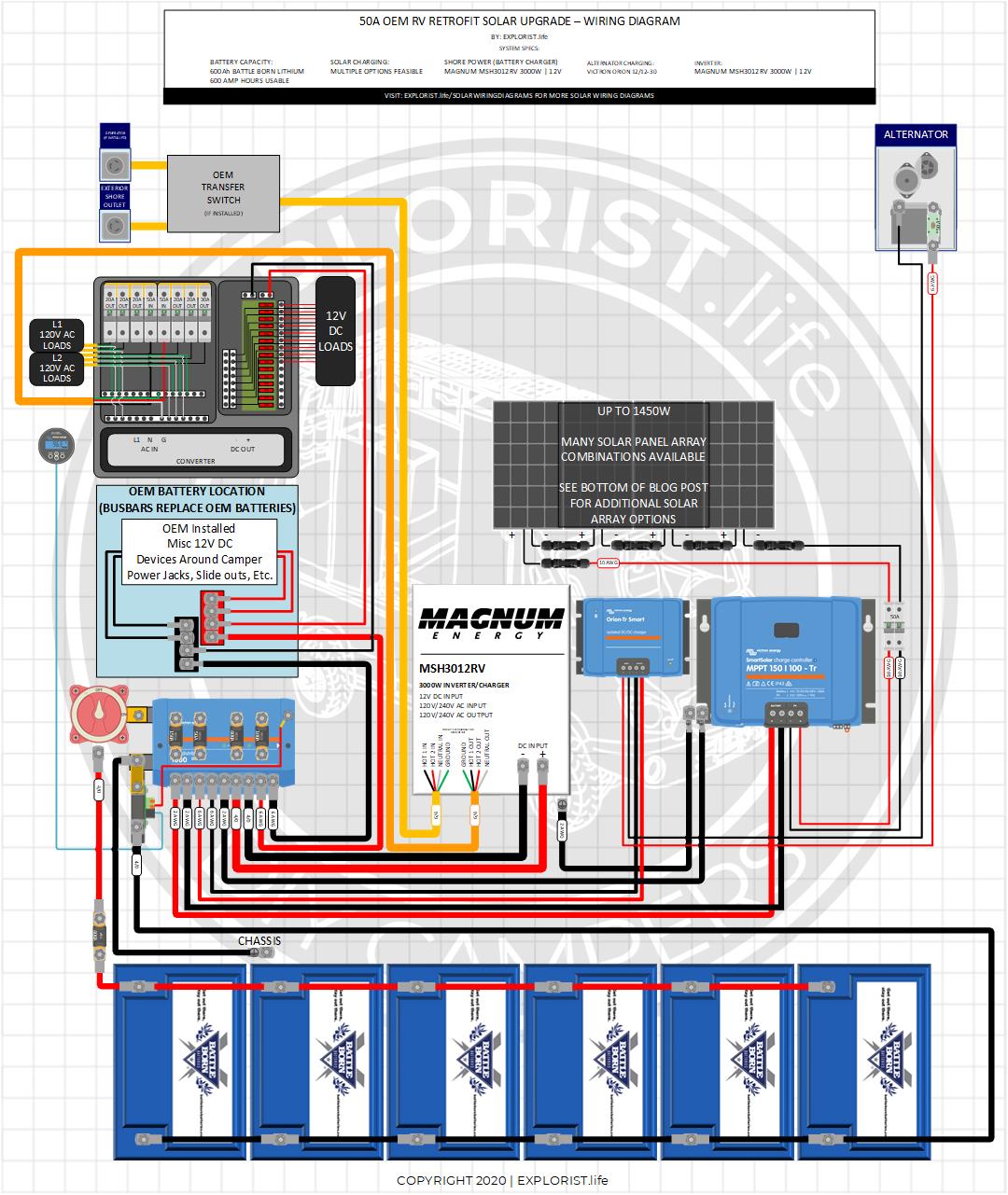
50a Camper Inverter W Solar Alternator Charging High Res Wiring Diagram Explorist Life from www.explorist.life Get the boost you need to power up heavy duty appliances with an rv inverter from camping world. Diy wiring diagrams for 100w, 200w, 300w, 400w, 600w, 800w kits. Lượt xem 39 n2030 năm trước. Use the recommended size or larger. Diy camper solar wiring diagrams. Hover your mouse / click on any product to learn more. Iec c13 wiring diagram injector wiring harness 60 diesel iceshanty wiring diagram inductive proximity sensor block diagram industrial pump diagram impala fuse box ideas to cover fuse box ignition switch wiring diagram rv inverter installation location advice forest river forums. When and how to use a wiring.
F electrical wiring diagram (system circuits).
2006 toyota avalon wiring diagrams. Confused about wiring the electrical system in your van build? None, 1000w, 1500w or 2000w. Get the boost you need to power up heavy duty appliances with an rv inverter from camping world. The high frequency ac to low frequency ac converter circuit using the irs2453d chip should be wired appropriately as shown in the diagram. We mounted our inverter to the outside of the partition that separates the electrical enclosure from the storage area under the bench. The diagram offers visual representation of an electrical structure. A wiring diagram is a simplified traditional photographic depiction of an electric circuit. Please note you can convert this ferrite core inverter to any desired wattage, right from 100 watt to 5 kva or as per your own preference. Inverter fridge wiring diagram in hindi, how to inverter fridge wiring diagram in hindi inverter fridge ka wiring diagram kaise kare. Rv information, tips, how to, tours, new products, and your general topics surrounding rving is what we inverters for rvs add a tremendous amount of flexibility and functionality. What's an rv inverter and do you need one? Great new deals every week and watch our on demand videos and live stream here!
The ultimate rv show 10 week national tour begins now! This gives a good explanation of the difference between a schematic and wiring diagram. Inverters convert dc to ac. How to install an automatic rv transfer switch. Get the boost you need to power up heavy duty appliances with an rv inverter from camping world.
Diagram Magnetek Rv Inverter Wiring Diagram Full Version Hd Quality Wiring Diagram Ardiagramlg Mercatutto It from tops-stars.com Related searches for inverter wiring diagram pdf power inverter wiring diagraminverter generator wiring diagrammarine inverter wiring diagramlighting inverter wiring diagramrv inverter wiring diagramelectrical inverter wiringpower inverter schematic diagramemergency lighting inverter. An inverter is less efficient. View our rv wiring diagram to understand how an rv electrical system works and the diference between ac and dc power. Wiring diagrams, spare parts catalogue, fault codes free download. This gives a good explanation of the difference between a schematic and wiring diagram. Cd 4047 is a low power cmos astable/monostable multivibrator ic. It shows how the electrical wires are interconnected and can also show where fixtures and components may be connected to the system. Confused about wiring the electrical system in your van build?
Inverter fridge wiring diagram in hindi, how to inverter fridge wiring diagram in hindi inverter fridge ka wiring diagram kaise kare.
Today we install the we have diagrams on the website to be able to install it with a manual or automatic switch or install. Use the recommended size or larger. Dc reactor to improve input power. The high frequency ac to low frequency ac converter circuit using the irs2453d chip should be wired appropriately as shown in the diagram. Get the boost you need to power up heavy duty appliances with an rv inverter from camping world. Related searches for inverter wiring diagram pdf power inverter wiring diagraminverter generator wiring diagrammarine inverter wiring diagramlighting inverter wiring diagramrv inverter wiring diagramelectrical inverter wiringpower inverter schematic diagramemergency lighting inverter. Iec c13 wiring diagram injector wiring harness 60 diesel iceshanty wiring diagram inductive proximity sensor block diagram industrial pump diagram impala fuse box ideas to cover fuse box ignition switch wiring diagram rv inverter installation location advice forest river forums. Interactive & comprehensive electrical wiring diagram for diy camper van conversion. Minimum recommended cable sizing chart†. It makes the procedure for assembling circuit easier. An inverter is less efficient. Hover your mouse / click on any product to learn more. The diagram offers visual representation of an electrical structure.
A wiring diagram is a simplified traditional photographic depiction of an electric circuit. After making the decision on your rv inverter purchase, you may just need to start your diy rv the inverter manual will probably suggest a wire size. The ultimate rv show 10 week national tour begins now! It makes the procedure for assembling circuit easier. You can see examples of this by directing your.
Installing Aftermarket Inverter Forest River Forums from i.imgur.com Diy camper solar wiring diagrams. Wiring inverter to house wiring diagram database, alt_image rv inverter install four different diy methods to get off, alt_image image result for rv converter charger wiring diagram buy, alt_image How to choose the right inverter for your rv and how to go about installing it? A wiring diagram is a simple visual representation of the physical connections and physical layout of an electrical system or circuit. They do the same thing as converters, but it is reversed. What's an rv inverter and do you need one? Diy wiring diagrams for 100w, 200w, 300w, 400w, 600w, 800w kits. Use the recommended size or larger.
2006 toyota avalon wiring diagrams.
Many installers prefer wiring diagrams. Here it is wired as an astable multivibrator. It shows how the electrical wires are interconnected and can also show where fixtures and components may be connected to the system. A wiring diagram is a simple visual representation of the physical connections and physical layout of an electrical system or circuit. Related searches for inverter wiring diagram pdf power inverter wiring diagraminverter generator wiring diagrammarine inverter wiring diagramlighting inverter wiring diagramrv inverter wiring diagramelectrical inverter wiringpower inverter schematic diagramemergency lighting inverter. How to choose the right inverter for your rv and how to go about installing it? None (loads are connected directly to the. Great new deals every week and watch our on demand videos and live stream here! How to install an automatic rv transfer switch. An inverter is less efficient. Single door lg inverter refrigerator fridge wiring diagram wiring diagram=. F electrical wiring diagram (system circuits). Lượt xem 39 n2030 năm trước.
Fonyód Tűz - Voksán Virág | NLCafé - A katasztrófavédelem által közzétett térkép szerint az alábbi területen pusztít a tűz . A tűzoltók a terület kilencven százalékát körülhatárolták. Hungary / somogy / fonyyd / fonyód. Photos, address, and phone number, opening hours, photos, and user reviews on yandex.maps. Internet, ar condicionado, tv, antena parabólica ou televisão por cabo, estacionamento, aquecimento quartos: 7,434 likes · 192 talking about this. Reklamlara boğulmadan, farklı kaynaklardan tamamen tarafsız içerikleri okuyun. Situated in fonyod, this apartment building is within 2 mi (3 km). Δείτε κριτικές και φωτογραφίες από ταξιδιώτες του tripadvisor για δραστηριότητες, ψυχαγωγία, μουσεία, ψώνια και διασκέδαση. Fonyód külterületén, a turul utca közelében kapott lángra a nádas, amelynek eloltásához először a keszthelyi, a siófoki, a marcali hivatásos, a balatonboglári önkormányzati, valamint a fonyódi önkéntes. A fonyód média nonprofit kft. ...
Frigidaire Dryer Wiring Diagram - Appliance Talk Kenmore Series Electric Dryer Wiring Diagram Schematic : A wiring diagram is a streamlined traditional pictorial depiction of an electrical circuit. . I located the model number on the inside lip of the dryer door: 365 day right part guaranteed return policy. Applianceaid.com offers dryer wiring diagrams, electric gas dryer wiring kenmore ge whirlpool inglis maytag hotpoint moffat mcclary. The difference in most is the electronic control board that you use to set the controls. Looking for info about frigidaire wiring schematics? I googled frigidaire affinity dryer squeak. Frigidaire frigidaire/electric dryer leq6000es2 my repair & advice. Assortment of frigidaire dryer wiring diagram. Joined oct 5, 2019 127. Repair your frigidaire dryer wire, receptacle & wire connector for less. Air Center Frigidaire Dryer Wiring Diagram from www.p...
Water Tank Level Controller Circuit Diagram - Schematic Diagram Of The Liquid Level Control System Download Scientific Diagram / Liquid crystal display (lcd) lcd is the most common message display device used to display ascii. . Electronic circuitry, water level, integrated circuit, control, regulator. You are able to utilize this motor. I made the water level indicator circuit with ic uln 2003.2nd circuit for pump control made with ic555. A simple but very reliable and effective water level controller circuit diagram is shown here. Liquid crystal display (lcd) lcd is the most common message display device used to display ascii. The circuit diagram of the water level controller using arduino is shown below. The probes are arranged in such a way that they sense ¼th, 1/2, ¾th and even full levels as they are placed with equal spacing one. Water level indicator controller using pic microcontroller. The circuit uses 6 transistors, 1 ne555 timer ic, a relay and few passiv...


Komentar
Posting Komentar