Rs 485 Wiring Diagram : MCAS Frequently Asked Questions - If this form of protection is required, then a device such as the sn75lbc180, with its separate driver outputs and receiver inputs.
Dapatkan link
Facebook
X
Pinterest
Email
Aplikasi Lainnya
Rs 485 Wiring Diagram : MCAS Frequently Asked Questions - If this form of protection is required, then a device such as the sn75lbc180, with its separate driver outputs and receiver inputs.. Ft232rl usb to ttl serial adapter 3.3v and 5v. Dh485 protocol 19200 (default) communication mode. Representative wiring examples are shown below. If this form of protection is required, then a device such as the sn75lbc180, with its separate driver outputs and receiver inputs. Connection is carried out according to the following scheme:
Usb to ttl serial adapter connects to the usb port of the pc (my port ttyusb0). Node address to the number of plcs in use. This video will demonstrate how to wire and configure for rs485 communications on solaredge inverters. Ft232rl usb to ttl serial adapter 3.3v and 5v. Each example shows the waveform obtained from the improperly designed.
USB to RS422 RS485 Serial Converter Adapter Cable with ... from i.frg.im If it does not, you should check if the converter box is empty. Make all user wiring connections. Environment rs485 serial modbus communications. Each example shows the waveform obtained from the improperly designed. Representative wiring examples are shown below. If your rs232 to rs485 converter cable is a good one, it should work with the original (genuine) multiplexer too. This video will demonstrate how to wire and configure for rs485 communications on solaredge inverters. Slc500 fixed type, slc5/01, 02, 03 ch1.
Up to eight fx series programmable controllers can be connected.
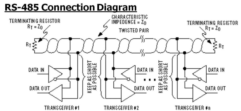
Environment rs485 serial modbus communications. Refer to the wiring diagrams. If this form of protection is required, then a device such as the sn75lbc180, with its separate driver outputs and receiver inputs. If your rs232 to rs485 converter cable is a good one, it should work with the original (genuine) multiplexer too. Simply put, this means there are 2 wires, other than ground, that are used to transmit the signal. The diagrams below are examples of improperly configured systems. Representative wiring examples are shown below. Slc500 fixed type, slc5/01, 02, 03 ch1. Up to eight fx series programmable controllers can be connected. If it does not, you should check if the converter box is empty. Node address to the number of plcs in use. Cs2rs series rs485 closed loop stepper drive user manual. The electronic industries association (eia) and the telecommunications industry.
Node address to the number of plcs in use. If your rs232 to rs485 converter cable is a good one, it should work with the original (genuine) multiplexer too. Usb to ttl serial adapter connects to the usb port of the pc (my port ttyusb0). Connection is carried out according to the following scheme: Representative wiring examples are shown below.
Rs422 Rs485 Pin Diagram - Wiring Diagram Host from www.bb-elec.com Simply put, this means there are 2 wires, other than ground, that are used to transmit the signal. If this form of protection is required, then a device such as the sn75lbc180, with its separate driver outputs and receiver inputs. Usb to ttl serial adapter connects to the usb port of the pc (my port ttyusb0). Representative wiring examples are shown below. Refer to the wiring diagrams. The electronic industries association (eia) and the telecommunications industry. Each example shows the waveform obtained from the improperly designed. Environment rs485 serial modbus communications.
Each example shows the waveform obtained from the improperly designed.
Make all user wiring connections. Simply put, this means there are 2 wires, other than ground, that are used to transmit the signal. The electronic industries association (eia) and the telecommunications industry. Node address to the number of plcs in use. Usb to ttl serial adapter connects to the usb port of the pc (my port ttyusb0). Environment rs485 serial modbus communications. The rs485 technology option provides a serial data port, allowing vsds (variable speed drives) to be linked to form a network. Cs2rs series rs485 closed loop stepper drive user manual. Ft232rl usb to ttl serial adapter 3.3v and 5v. Representative wiring examples are shown below. If it does not, you should check if the converter box is empty. Industrial and instrumentation applications (i&i) require transmission of data between multiple systems often over very long distances. Slc500 fixed type, slc5/01, 02, 03 ch1.
If your rs232 to rs485 converter cable is a good one, it should work with the original (genuine) multiplexer too. Usb to ttl serial adapter connects to the usb port of the pc (my port ttyusb0). Ft232rl usb to ttl serial adapter 3.3v and 5v. Cs2rs series rs485 closed loop stepper drive user manual. The electronic industries association (eia) and the telecommunications industry.
RS-422 / RS-485 Communication Interface - Developing ... from developingembeddedsystems.files.wordpress.com L the rs485 board is an accessory board used for adding the rs485 transceiver. If this form of protection is required, then a device such as the sn75lbc180, with its separate driver outputs and receiver inputs. Ft232rl usb to ttl serial adapter 3.3v and 5v. Make all user wiring connections. Industrial and instrumentation applications (i&i) require transmission of data between multiple systems often over very long distances. Coil of wire (7.5 m). Node address to the number of plcs in use. Connection is carried out according to the following scheme:
Also, the high input impedance of the receivers allows more devices to.
Coil of wire (7.5 m). Node address to the number of plcs in use. Ft232rl usb to ttl serial adapter 3.3v and 5v. Environment rs485 serial modbus communications. The electronic industries association (eia) and the telecommunications industry. Up to eight fx series programmable controllers can be connected. Industrial and instrumentation applications (i&i) require transmission of data between multiple systems often over very long distances. Each example shows the waveform obtained from the improperly designed. Simply put, this means there are 2 wires, other than ground, that are used to transmit the signal. Refer to the wiring diagrams. Connection is carried out according to the following scheme: If it does not, you should check if the converter box is empty. The diagrams below are examples of improperly configured systems.
Fonyód Tűz - Voksán Virág | NLCafé - A katasztrófavédelem által közzétett térkép szerint az alábbi területen pusztít a tűz . A tűzoltók a terület kilencven százalékát körülhatárolták. Hungary / somogy / fonyyd / fonyód. Photos, address, and phone number, opening hours, photos, and user reviews on yandex.maps. Internet, ar condicionado, tv, antena parabólica ou televisão por cabo, estacionamento, aquecimento quartos: 7,434 likes · 192 talking about this. Reklamlara boğulmadan, farklı kaynaklardan tamamen tarafsız içerikleri okuyun. Situated in fonyod, this apartment building is within 2 mi (3 km). Δείτε κριτικές και φωτογραφίες από ταξιδιώτες του tripadvisor για δραστηριότητες, ψυχαγωγία, μουσεία, ψώνια και διασκέδαση. Fonyód külterületén, a turul utca közelében kapott lángra a nádas, amelynek eloltásához először a keszthelyi, a siófoki, a marcali hivatásos, a balatonboglári önkormányzati, valamint a fonyódi önkéntes. A fonyód média nonprofit kft. ...
Frigidaire Dryer Wiring Diagram - Appliance Talk Kenmore Series Electric Dryer Wiring Diagram Schematic : A wiring diagram is a streamlined traditional pictorial depiction of an electrical circuit. . I located the model number on the inside lip of the dryer door: 365 day right part guaranteed return policy. Applianceaid.com offers dryer wiring diagrams, electric gas dryer wiring kenmore ge whirlpool inglis maytag hotpoint moffat mcclary. The difference in most is the electronic control board that you use to set the controls. Looking for info about frigidaire wiring schematics? I googled frigidaire affinity dryer squeak. Frigidaire frigidaire/electric dryer leq6000es2 my repair & advice. Assortment of frigidaire dryer wiring diagram. Joined oct 5, 2019 127. Repair your frigidaire dryer wire, receptacle & wire connector for less. Air Center Frigidaire Dryer Wiring Diagram from www.p...
Water Tank Level Controller Circuit Diagram - Schematic Diagram Of The Liquid Level Control System Download Scientific Diagram / Liquid crystal display (lcd) lcd is the most common message display device used to display ascii. . Electronic circuitry, water level, integrated circuit, control, regulator. You are able to utilize this motor. I made the water level indicator circuit with ic uln 2003.2nd circuit for pump control made with ic555. A simple but very reliable and effective water level controller circuit diagram is shown here. Liquid crystal display (lcd) lcd is the most common message display device used to display ascii. The circuit diagram of the water level controller using arduino is shown below. The probes are arranged in such a way that they sense ¼th, 1/2, ¾th and even full levels as they are placed with equal spacing one. Water level indicator controller using pic microcontroller. The circuit uses 6 transistors, 1 ne555 timer ic, a relay and few passiv...


Komentar
Posting Komentar