Mass Air Flow Sensor Wiring Diagram - Toyota Maf Sensor Wiring Best Wiring Diagrams Versed Follow Versed Follow Ekoegur Es : F150, f250, f350, mustang, crown victoria
Dapatkan link
Facebook
X
Pinterest
Email
Aplikasi Lainnya
Mass Air Flow Sensor Wiring Diagram - Toyota Maf Sensor Wiring Best Wiring Diagrams Versed Follow Versed Follow Ekoegur Es : F150, f250, f350, mustang, crown victoria. Then, measure the voltage between maf sensor connector terminals c and d. I also show you how you can figure out the wires without a wiring diagram. The mass air flow (maf) sensor wiring diagram and info in this page apply only to: 5 wire mass air flow sensor wiring diagram from troubleshootmyvehicle.com effectively read a electrical wiring diagram, one has to find out how the particular components within the system operate. You can buy the maf sensor for your suzuki sidekick (geo tracker) in just about any auto parts store but you'll spend a whole lot more because they mark it up quite a bit.
Maf sensor connector pinout on l, l, l engines. With the engine running at idle, use a dvom to verify that there are at least 10.5 volts between terminals a and b of the maf sensor connector. If you are going to replace the maf yourself, then i'd always recommend buying an oem mass air flow sensor. The lt blu/red wire outputs the maf signal to the pcm. Here is a video on how you can test your maf sensor using a basic $5 multimeter.
97 Ranger Maf Sensor Wiring Diagram Wiring Diagram Schema Week Energy A Week Energy A Atmosphereconcept It from www.fordforum.com On the other hand, this diagram is a simplified version of this arrangement. This makes the procedure for assembling circuit simpler. Check the terminals for a loose wire or bad connection. You can buy the maf sensor for your suzuki sidekick (geo tracker) in just about any auto parts store but you'll spend a whole lot more because they mark it up quite a bit. Heated platinum wire, suspended in the engine's air stream. I need to identify the iat sensor wires on my 4/17/ 1/1/ hi, can you tell me the two iat sensor wires on a nissan 1/14/ 1/1/ the engine. 2005 cadillac srx srx timing chain. For instance , if a module is powered up and it also sends out the signal of half the voltage in addition to the technician will not know this, he.
The mass air flow sensors converts the amount of air drawn into the engine into a voltage signal.
Heated platinum wire, suspended in the engine's air stream. F150, f250, f350, mustang, crown victoria We have gathered lots of pictures, ideally this picture is useful for you, and aid you in discovering the solution you are looking for. 2005 cadillac srx srx timing chain. This makes the procedure for assembling circuit simpler. Check the terminals for a loose wire or bad connection. For example , in case a module is usually powered up and it sends out the signal of fifty percent the voltage plus the technician would not know this, he'd. Here is a video on how you can test your maf sensor using a basic $5 multimeter. The wire colors and the connections mentioned to the ecu are from a 66kw agr and a 81kw ahf engine. Then he decided to take the 6 prong maf sensor off my car and put a 4 prong maf sensor on, he connected 4 of the 6 wires from the maf wiring harness to the replacement 4 prong sensor and put 2 of the wires ( 1 at each end) into a loop saying these 2 were just open loop and not needed, he later cut off the 2 wires, 1 at each end, he said they. Add your vehicle in manage my vehicles. The primary components of the maf sensor are thermistor, a platinum hot wire, and an electronic control circuit. For instance , if a module is powered up and it also sends out the signal of half the voltage in addition to the technician will not know this, he.
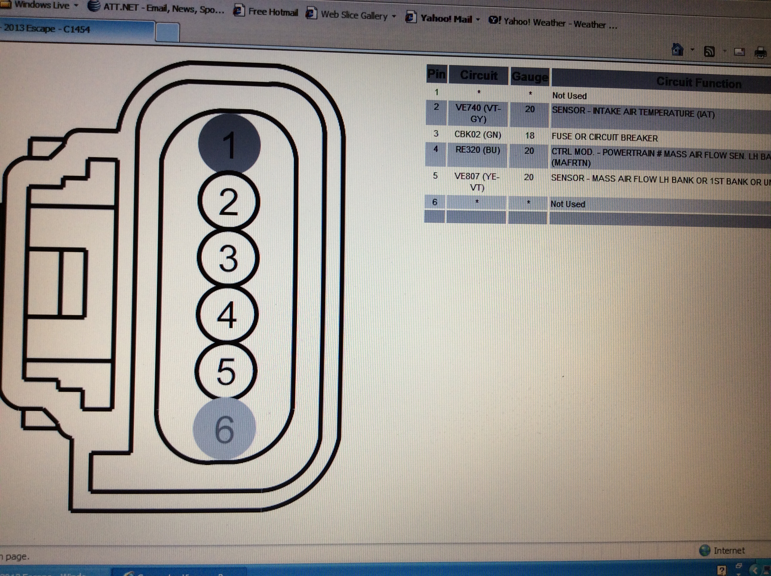
If you are going to replace the maf yourself, then i'd always recommend buying an oem mass air flow sensor. Mass air flow sensor testing. Pin description wire color connected to On the other hand, this diagram is a simplified version of this arrangement. Maf sensor & wiring diagrams maf sensor & wiring diagrams amazon printed books the maf or mass air flow sensor is a main input to the ecm or engine puter form air how to test a mass air flow maf sensor without a how to test a maf sensor using a basic multimeter without having to look up a wiring diagram if you liked this video you may find these other
Diagram Mazda 323 Mass Air Flow Wiring Diagrams Full Version Hd Quality Wiring Diagrams Bgwiringx19 Pergotende Roma It from www.untpikapps.com If the maf sensor has 6 wires, then this is a dead giveaway that it has the air temp sensor integrated inside. Replacing a mass air flow sensor is fairly straight forward, so most of the cost comes from the cost of the part, and not the labor. Such a reading indicates that the power input to the sensor is correct. F150, f250, f350, mustang, crown victoria The mass air flow (maf) sensor wiring diagram and info in this page apply only to: Then he decided to take the 6 prong maf sensor off my car and put a 4 prong maf sensor on, he connected 4 of the 6 wires from the maf wiring harness to the replacement 4 prong sensor and put 2 of the wires ( 1 at each end) into a loop saying these 2 were just open loop and not needed, he later cut off the 2 wires, 1 at each end, he said they. The second picture is the wiring diagram for the maf/iat assembly. On the other hand, this diagram is a simplified version of this arrangement.
Pin description wire color connected to
Mass air flow sensor testing. With the engine running at idle, use a dvom to verify that there are at least 10.5 volts between terminals a and b of the maf sensor connector. Mass air flow sensor page content: Step by step guide on how an automotive mass air flow sensor (maf) works. Add your vehicle in manage my vehicles. This makes the procedure for assembling circuit simpler. Mass air flow (maf) sensors 32 manual cautions when working around the air bag components or wiring. For example , in case a module is usually powered up and it sends out the signal of fifty percent the voltage plus the technician would not know this, he'd. The primary components of the maf sensor are thermistor, a platinum hot wire, and an electronic control circuit. The mass air flow sensors converts the amount of air drawn into the engine into a voltage signal. I need to identify the iat sensor wires on my 4/17/ 1/1/ hi, can you tell me the two iat sensor wires on a nissan 1/14/ 1/1/ the engine. 5 wire mass air flow sensor wiring diagram from troubleshootmyvehicle.com effectively read a electrical wiring diagram, one has to find out how the particular components within the system operate. If you are going to replace the maf yourself, then i'd always recommend buying an oem mass air flow sensor.
3 wire maf sensor you are welcome to our site this is images about 3 wire maf sensor posted by ella brouillard in 3 category on oct 23 2019. Hot wire (2) with diameter of 70μm is mounted in a measuring tube located before the throttle valve. Mass air flow wiring diagram, can i get one please? For instance , if a module is powered up and it also sends out the signal of half the voltage in addition to the technician will not know this, he. Maf sensor & wiring diagrams maf sensor & wiring diagrams amazon printed books the maf or mass air flow sensor is a main input to the ecm or engine puter form air how to test a mass air flow maf sensor without a how to test a maf sensor using a basic multimeter without having to look up a wiring diagram if you liked this video you may find these other
Subaru Maf Sensor Wiring Diagram Wiring Diagrams Auto Bite Board Bite Board Moskitofree It from ww2.justanswer.com The mass air flow sensors converts the amount of air drawn into the engine into a voltage signal. By continuing to use this site you consent to the use of cookies on your device as described in our cookie policy unless you have disabled them. You can buy the maf sensor for your suzuki sidekick (geo tracker) in just about any auto parts store but you'll spend a whole lot more because they mark it up quite a bit. I need to identify the iat sensor wires on my 4/17/ 1/1/ hi, can you tell me the two iat sensor wires on a nissan 1/14/ 1/1/ the engine. 2005 cadillac srx srx timing chain. Is not attained, check the wiring from terminal 3 to fuse panel, using an applicable wiring diagram. Maf sensor & wiring diagrams maf sensor & wiring diagrams amazon printed books the maf or mass air flow sensor is a main input to the ecm or engine puter form air how to test a mass air flow maf sensor without a how to test a maf sensor using a basic multimeter without having to look up a wiring diagram if you liked this video you may find these other Mass air flow sensor wiring schematic.
Then he decided to take the 6 prong maf sensor off my car and put a 4 prong maf sensor on, he connected 4 of the 6 wires from the maf wiring harness to the replacement 4 prong sensor and put 2 of the wires ( 1 at each end) into a loop saying these 2 were just open loop and not needed, he later cut off the 2 wires, 1 at each end, he said they.
Is not attained, check the wiring from terminal 3 to fuse panel, using an applicable wiring diagram. This makes the procedure for assembling circuit simpler. You can buy the maf sensor for your suzuki sidekick (geo tracker) in just about any auto parts store but you'll spend a whole lot more because they mark it up quite a bit. Hello, here are the mass air flow wiring diagrams with the engine diagrams included so. Mass air flow sensor wiring diagram location likewise oxygen sensor wiring color codes on kia o2 sensor. Bosch hot film air mass meter mass air flow maf brand new a mass air flow maf sensor without a wiring diagram usa maf air flow mass. Then he decided to take the 6 prong maf sensor off my car and put a 4 prong maf sensor on, he connected 4 of the 6 wires from the maf wiring harness to the replacement 4 prong sensor and put 2 of the wires ( 1 at each end) into a loop saying these 2 were just open loop and not needed, he later cut off the 2 wires, 1 at each end, he said they. Pierburg maf bosch maf converting mg/stroke to kg/hour pierburg mass air flow sensor. 3 wire maf sensor you are welcome to our site this is images about 3 wire maf sensor posted by ella brouillard in 3 category on oct 23 2019. Then, measure the voltage between maf sensor connector terminals c and d. For y f body mass air flow sensor replacement for bosch hot wire. 5 wire mass air flow sensor wiring diagram from troubleshootmyvehicle.com effectively read a electrical wiring diagram, one has to find out how the particular components within the system operate. Mass air flow sensor wiring schematic.
Fonyód Tűz - Voksán Virág | NLCafé - A katasztrófavédelem által közzétett térkép szerint az alábbi területen pusztít a tűz . A tűzoltók a terület kilencven százalékát körülhatárolták. Hungary / somogy / fonyyd / fonyód. Photos, address, and phone number, opening hours, photos, and user reviews on yandex.maps. Internet, ar condicionado, tv, antena parabólica ou televisão por cabo, estacionamento, aquecimento quartos: 7,434 likes · 192 talking about this. Reklamlara boğulmadan, farklı kaynaklardan tamamen tarafsız içerikleri okuyun. Situated in fonyod, this apartment building is within 2 mi (3 km). Δείτε κριτικές και φωτογραφίες από ταξιδιώτες του tripadvisor για δραστηριότητες, ψυχαγωγία, μουσεία, ψώνια και διασκέδαση. Fonyód külterületén, a turul utca közelében kapott lángra a nádas, amelynek eloltásához először a keszthelyi, a siófoki, a marcali hivatásos, a balatonboglári önkormányzati, valamint a fonyódi önkéntes. A fonyód média nonprofit kft. ...
Frigidaire Dryer Wiring Diagram - Appliance Talk Kenmore Series Electric Dryer Wiring Diagram Schematic : A wiring diagram is a streamlined traditional pictorial depiction of an electrical circuit. . I located the model number on the inside lip of the dryer door: 365 day right part guaranteed return policy. Applianceaid.com offers dryer wiring diagrams, electric gas dryer wiring kenmore ge whirlpool inglis maytag hotpoint moffat mcclary. The difference in most is the electronic control board that you use to set the controls. Looking for info about frigidaire wiring schematics? I googled frigidaire affinity dryer squeak. Frigidaire frigidaire/electric dryer leq6000es2 my repair & advice. Assortment of frigidaire dryer wiring diagram. Joined oct 5, 2019 127. Repair your frigidaire dryer wire, receptacle & wire connector for less. Air Center Frigidaire Dryer Wiring Diagram from www.p...
Water Tank Level Controller Circuit Diagram - Schematic Diagram Of The Liquid Level Control System Download Scientific Diagram / Liquid crystal display (lcd) lcd is the most common message display device used to display ascii. . Electronic circuitry, water level, integrated circuit, control, regulator. You are able to utilize this motor. I made the water level indicator circuit with ic uln 2003.2nd circuit for pump control made with ic555. A simple but very reliable and effective water level controller circuit diagram is shown here. Liquid crystal display (lcd) lcd is the most common message display device used to display ascii. The circuit diagram of the water level controller using arduino is shown below. The probes are arranged in such a way that they sense ¼th, 1/2, ¾th and even full levels as they are placed with equal spacing one. Water level indicator controller using pic microcontroller. The circuit uses 6 transistors, 1 ne555 timer ic, a relay and few passiv...


Komentar
Posting Komentar